The PoE Meter works with an easy to use API. To communicate with it, just open a serial port with the following settings:
- Baudrate - 115200
- Data bits - 8
- Parity - none
- Stop Bits - 1
To open the serial port we recommend:
- minicom - if you are using a linux/raspbian/opkg machine
- PuTTY - if you are using a windows machine
- pySerial if you are developing a python application
- MobaXterm - "Putty on steroids" for windows
To learn how to open the serial Port, please check the following sections minicom and MobaXterm , depending on your operating system. Once the connection is setup, head try getting the Firmware version to test it.
Minicom
To open a serial connection to an MDB-USB Interface or an MDB-Pi Hat with minicom, just issue the following command:
The following example opens the serial connection to /dev/ttyACM0, the actual name might differ in case there are other ACM devices. Nonetheless, only the index should change, and the port should always be named /dev/ttyACMX, with X varying.
xxxxxxxxxxsudo minicom -D /dev/ttyACM0 -b 115200Minicom can be installed using rpm package manager for your Linux distro. Below is an example of how to install it in latest Ubuntu.
xxxxxxxxxxsudo apt-get install minicom #Example of minicom installation using apt-getMobaXterm
MobaXTerm can be downloaded in this link. It is our recommendation for Windows users as it stores the Serial Port Definitions and auto detects available COM Ports. As a bonus it is also capable of starting SSH and Telnet sessions, storing the IP Addresses and usernames.
After installing the application, open it and follow these steps:
1 - Click Session(top left corner)
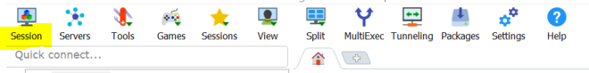
2 - Select "Serial" on the pop-up.
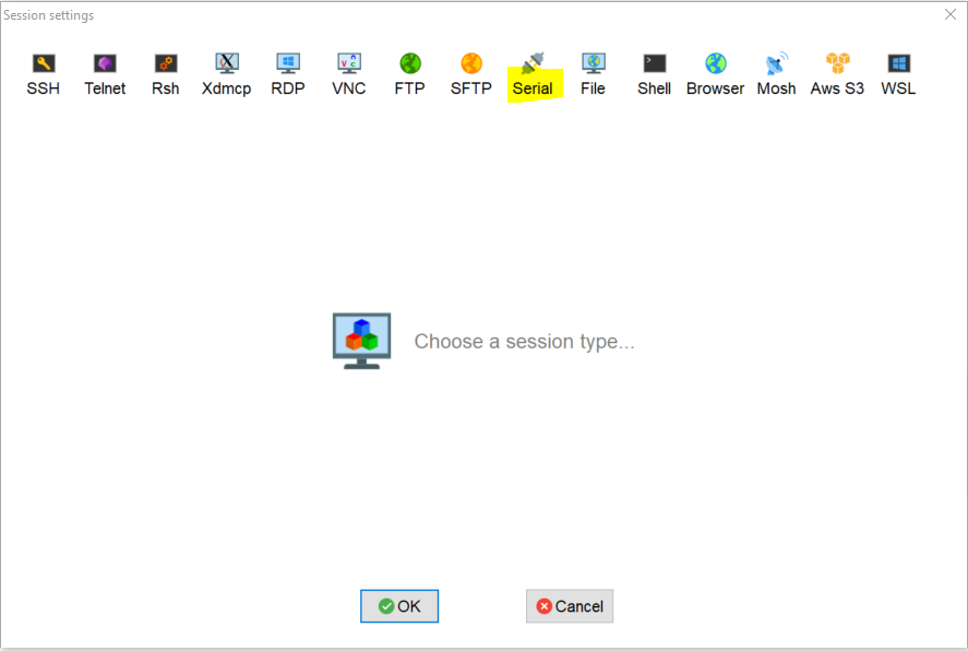
3 - Select the correct baudrate 115200

4 - Once previous step completed, on User Sessions (stored sessions) there will be a "Serial" Entry. To open it, just double click it.

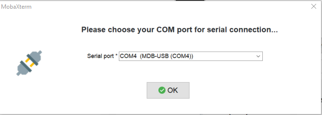
5 - Select COMX.
This example shows COM4, but it may differ in each situation. To learn what COM Port is the MDB-USB, use Device Manager from Windows and Unplug/Plug the MDB-USB. The corresponding COM port will be available only when you plug the MDB USB back into the computer.
All commands must be followed by a newline (\n)
Retrieve Version Info
xxxxxxxxxxVxxxxxxxxxxPoE_Meter V0.0.7 D0:FFFFC000:1:0:0Answer:
- PoE_Meter Vs.s.s Dxxxxxxxxxxxx
Where:
- s.s.s = firmware version
- xxxxxxxxxx = flash health
Retrieve Hardware Info
xxxxxxxxxxHxxxxxxxxxxH1.0 S383632521930511C4A3BD843Answer:
- Hx.x Syyyy
Where:
- x.x = hardware version
- yyyyyyyyyy = Micro-controller unique serial number
Display & Buttons Manual Control
Manual/Automatic Read Input
Inputs can be configured to automatic report, or manual read. The automatic report of the inputs can be configured with the following commands:
xxxxxxxxxxI0 #query inputsI1 #enable automatic status change reportI2 #disable automatic status change reportxxxxxxxxxxI2i,000F #all buttons not pressedxxxxxxxxxxI2i,000E #button 1 pressedi,000D #button 2 pressedi,000B #button 3 pressedi,0007 #button 4 pressedxxxxxxxxxxPress buttons 3 and 4 I0i,0003 #buttons 3 and 4 are pressed and 1 and 2 are releasedSet Display Status
Turn display on/off;
- Default:
- On, if communication with acquisition units is established;
- Off, if no communication with acquisition units is established and USB communication is detected;
- Whenever an USB command is received, following a disconnect/buffer-full or on initialization, display is turned-on and cleared;
xxxxxxxxxxSDS:0 #offSDS:1 #onIf the display was set to off and device changes to stand-alone mode, the display will be turned on
Set Display Color
Allows configuration of the Highlighted and Non-highlighted background and font colours
Configuration:
- 0 - Non-highlighted background color - default White;
- 1 - Non-highlighted text color - default Black;
- 2 - Highlighted background color - default Black;
- 3 - Highlighted text color - default White;
- 4 - Indicators background color - default Black;
- When the Non-highlighted background color is set, only the text area is set to Non-highlighted background color - “cleared”;
- When the indicators background color is set, the indicators area is “cleared”;
Allowed colours:
- R – Red
- G – Green
- B – Blue
- Y – Yellow
- O – Orange
- W – White
- K – Black
- V - Violet
- L - Light Blue
xxxxxxxxxxSDC:0,R #Set non-highlighted background color to redTo not compromise device working, for configuration options:
- 0 - use a maximum update rate of 180 ms;
- 4 - use a maximum update rate of 50 ms;
Set Display Text
Set the text to be displayed (one line at a time). The default is with no text and the maximum characters per line is 20, more will be discarded.
Configuration:
- Line - 1 to 6;
- Highlight status
- 1 - Highlighted
- 0 - Non-highlighted
- When a new highlighted line is received, application automatically changes the previous highlighted to non-highlighted;
- Display string is encoded as hex values;
xxxxxxxxxxSDT:2,0,57656C636F6D65 #Send “Welcome” to line 2 as non-highlightedSDT:2,0,20 #Clear line 2 as non-highlightedTo clear one line, just send one “space” (0x20)
To not compromise device working, use a maximum text line update rate of 200 ms
Set Display Indicator
Allow individual configuration of the 12 display indicators. The default is All inactive (black);
Configuration
- Display indicator - 1 to 12;
Allowed colours
- R – Red;
- G – Green;
- B – Blue;
- Y – Yellow;
- O – Orange;
- W – White;
- K – Black;
- V - Violet;
- L - Light Blue;
xxxxxxxxxxSDI:5,R #Set indicator 5 to redFor clearing, send the current configured Non-highlighted background color - default (black)
To not compromise device working, use a maximum id update rate of 5 ms
Hardware status indication in stand-alone mode
Only available after calibration ("normal" mode) and if in stand-alone mode
Indicators
- ID 1 - Working mode
- ID 9 - Acquisition unit 1 status
- ID 10 - Acquisition unit 2 status
- ID 11 - RTC status
- ID 12 - uSD card status
Colors
- Yellow - Testing
- Green - Ok
- Red - Fail
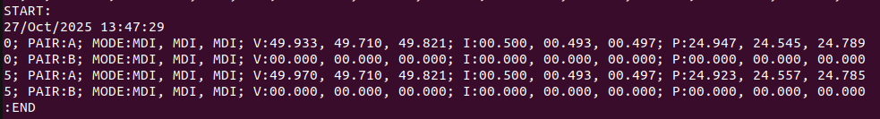
LOG mode data sending
- Dump log file via USB;
- Send a start "frame" - "START:";
- Send the initial timestamp "DD/MM/YYYY:HH:MM:SS" in the second line followed by data starting in the third line;
- Every data chunk is sent with the same format as for Reporting using interval mode, except it does not send "r2" nor aggregation interval, it just sends the offset (in seconds) from the initial timestamp;
- Send an end "frame" - ":END" in the line after the last data;
- After sending the full file, existing file is deleted;
- If no log file exists, an error is sent - "ERR01";
- While logging data sending is in progress, no other data is sent through USB, but after finishing sending logging data, previous configuration is restored, so if PoE meter was configured to send data (readings or inputs auto-report), it will start to send it again.
Exit command
The Exit command can only be used after calibration to exit USB mode back to stand-alone mode, set Report mode off, set stand-alone mode interval to 1 second, disable inputs auto-report and reset Display colors to defaults
xxxxxxxxxxXAnswers
Following is a list of answers that can be received:
| Answer | Description |
|---|---|
| OK | Ok |
| ERR01 | Unknown or invalid command |
| ERR02 | Invalid parameter(s) to the command (number of parameters wrong) |
| ERR03 | Invalid IO address (not 1..2) or whatever is allowed in the command |
| ERR04 | Invalid Value (for example, for an “SDS” command a value of 2 is sent) |