Search
VEMIO 1 - LAYOUT
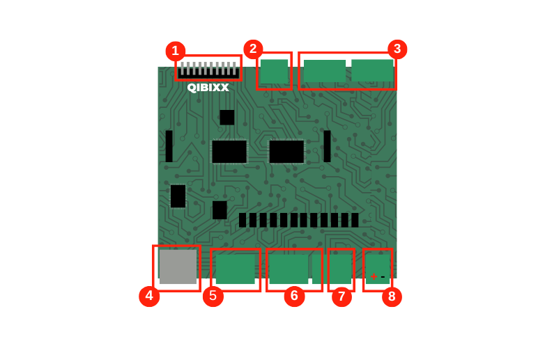
| Connector | Name | Description |
|---|---|---|
| 1 | Keyboard Output | Used for Keypad Simulator, up to 4x4 matrix size. Note that these pins are outputs in VEMIO, but will be inputs in the device that is to be controlled by the simulated keyboard. |
| 2 | Sensor Column | Unused. |
| 3 | 8 Digital Inputs | Active low inputs that can be read by VEMIO. |
| 4 | USB | This connector is used for data communication with the host and also powers the unit (5V, up to 500mA) |
| 5 | Analog Inputs | Feed the ADC to be read by the VEMIO. Input must not be higher than 5V. |
| 6 | 8 Driver High Outputs | When active (Ox=1 , with x being the pin number) , the Voltage level of this output will be pulled to V+ , which can range from 9 to 24V. |
| 7 | 4 Driver Low Outputs | When active (Ox=1 , with x being the pin number) , the Voltage level of this output will be pulled to Ground. |
| 8 | Power | Supports a DC power supply in the range of 9V-24V |
VEMIO 2 - LAYOUT
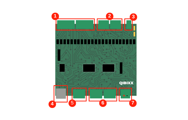
| Connector | Name | Description |
|---|---|---|
| 1 | 11 Driver Low Outputs | When active (Ox=1 , with x being the pin number) , the Voltage level of this output will be pulled to Ground. |
| 2 | 8 Driver High Outputs | When active (Ox=1 , with x being the pin number) , the Voltage level of this output will be pulled to V+ , which can range from 9 to 24V. |
| 3 | Power | Supports a DC power supply in the range of 9V-24V |
| 4 | USB | This connector is used for data communication with the host and also powers the unit (5V, up to 500mA) |
| 5 | Relays | 2 Relays that can be driven by VEMIO2 |
| 6 | 8 Digital Inputs | Active low inputs that can be read by VEMIO. |
| 7 | Temperature Sensor | 1 Wire input, typically used for a Temperature Sensor , but supports other 1 Wire Sensors. |