This page will Describe How the API for VEMIO can be used to sense its inputs and control its outputs. Before going into those details, it is important to note that VEMIO's API follows a mapping as described in IO Mapping.
As usual, VEMIO follows Qibixx' Common serial Protocol Rules:
End of Line indicated by carriage return (\r), line feed (\n), or both.
a single (capitalized) character indicates a command, followed by eventual parameters. NOTE: the device will also accept noncapitalized commands.
Answers follow the same principle, the device always sends and the answer messages start with a small (non-capitalised) letter.
Software Version
The response to this command wil be VEMIO H0X VY.YY, where X is the hardware version (1 or 2) and Y.YY its the software version.
Activate Output (VEMIO 1)
The following commands only set the logical value of the Output to 0 or 1. The Voltage level of the Given Output actually depends if it is an Active High or Active Low Output. The Output Pin Mapping to API Index is provided below below.
The response from VEMIO is a 32 bit word shown in HEX format. aa shows the values of outputs 1 to 8 (API index, not necessarily the Pin Number on the Board), bb shows outputs 9 to 16 , cc is not used , and dd is used for the outputs 25 to 32.
Some outputs are specific to VEMIO2, like the Relay and LED Outputs. The following example shows how to Enable and Disable these outputs. These outputs are shown in the second block of the output and its default value is c0 (1100 in Binary), since the LED bits (15 and 16) are default with value 1 and the relay bits (13 and 14) are default to 0.
Activate Output (VEMIO 2 - Software Version Below 2.0)
VEMIO 2 has the Driver Low and Driver Hight Outputs flipped.
Vemio 2 | Output Command |
|---|---|
Driver Low 1 | O12,1 |
Driver Low 2 | O11,1 |
Driver Low 3 | O10,1 |
Driver Low 4 | O9,1 |
Driver Low 5 | O8,1 |
Driver Low 6 | O7,1 |
Driver Low 7 | O6,1 |
Driver Low 8 | O5,1 |
Driver Low 9 | O4,1 |
Driver Low 10 | O3,1 |
Driver Low 11 | O2,1 |
Driver Low 12 | O1,1 |
Driver Hight 1 | O32,1 |
Driver Hight 2 | O31,1 |
Driver Hight 3 | O30,1 |
Driver Hight 4 | O29,1 |
Driver Hight 5 | O28,1 |
Driver Hight 6 | O27,1 |
Driver Hight 7 | O26,1 |
Driver Hight 8 | O25,1 |
Read Digital Inputs
The Inputs on VEMIO1 and VEMIO2 are active low, meaning that they need to be pulled to Ground in order to be detected in the API.
Inputs can be configured to automatic report, or manual read. The automatic report of the inputs can be configured with the following commands:
When the Automatic Input Report is enabled, each time that one of the inputs changes its level, all inputs will be reported in the serial port, like in the example below.
When the Automatic Input Report is disabled, the inputs can be read with the following commands. Although both commands are supported, their respective behavior does not show any difference.
Read Analog Inputs (VEMIO 1)
VEMIO 1 has 2 10 bit (approximately 4.8 mV resolution) Analog to Digital Converters that can be used to read the Analog Input. The Analog Input can be read using:
The read response is returned as 2 16 bit HEX numbers, corresponding to the value read from each of the inputs. In the example below, Analog Input was 5V on input 1 and 0V on input 2 (Analog Input 2 and 3, according to pin numbering on the board).
Monitor Current Output (VEMIO2)
Depending on the number of outputs that are activated at a given instant, the current being drawn by the Output loads may vary. This current could be measured using the following command.
The output current measure can be approximate by I = 0.0009 * Current(decimal) - 0.007 . When the current is read, three readings are shown, where the first is for active low outputs, the second is for active high outputs and the third is unused.
Read 1 Wire Sensor (VEMIO 2)
VEMIO2 is equipped with a 1-Wire Sensor input that can be used for instance to plug a Temperature Sensor. To read the value from this Sensor, the following command can be used:
This example refers to a specific sensor. Results may differ depending on the data being sent by the sensor in use.
Emulate Keypad (VEMIO1)
VEMIO 1 is equipped with a Keypad Simulator that can be used to replace up to 4x4 Matrix Keyboards. When used, it can emulate short key presses at any point of the Keypad matrix.
The keys can be activated with the following comand:
In the command above, aa is an 8 bit hexadecimal word, where the bit combination is an instruction to VEMIO1. The bits are mapped to pins as follows:
Pins | Description/Instructions |
|---|---|
Bits 0 .. 1 | Select which matrix column to activate. Accepts 0,1,2,3 to select up to 4 columns. |
Bit 2 | Do Not Use , should be set to 0 |
Bit 3 | Set to 1 to engage and 0 to disengage the Keypad Simulator. |
Bits 4 .. 5 | Select which matrix row to activate. Accepts 0,1,2,3 to select up to 4 rows. |
Bit 6 | Do Not Use , should be set to 0 |
Bit 7 | Do not use, must be set to 1 |
So let's assume we have a 4x4 keyboard like the following and we want to emulate it with VEMIO1.

This keyboard has 3 columns and 4 rows (rows count from top to bottom and columns from left to right). Now let's see in the example below how we could type "1, Enter" in this keyboard.
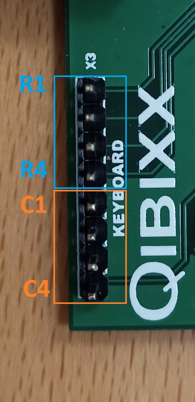
Note that the wiring is a responsibility of the Buyer. The following picture shows how the Pins on VEMIO1 are mapped to API Pins.